The modern charging system hasn't changed much
in over 40 years. It consists of the alternator,
regulator (which is usually mounted inside the alternator) and
the interconnecting wiring.
The purpose of the charging system is to
maintain the charge in the vehicle's battery, and to provide
the main source of electrical energy while the engine is
running.
If the charging system stopped working, the battery's charge would soon be depleted, leaving the car with
a "dead battery." If the battery is weak and the
alternator is not working, the engine may not have enough
electrical current to fire the spark plugs, so the engine will stop running.
If the battery is "dead", it does
not necessarily mean that there is anything wrong with it.
It is just depleted of its charge. It can be brought
back to life by recharging it with a battery charger, or by
running the engine so that the alternator can charge it.
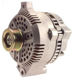
The main component in the charging system is
the
ALTERNATOR.
The alternator is a generator that produces Alternating
Current (AC), similar to the electrical current in your
home. This current is immediately converted to Direct
Current (DC) inside the alternator. This is because all
modern automobiles have a 12 volt, DC electrical system.
A
VOLTAGE
REGULATOR regulates the charging voltage that the
alternator produces, keeping it between 13.5 and 14.5 volts to
protect the electrical components throughout the vehicle.
There is also a system to warn the driver if something is not right with the charging system. This
could be a dash mounted voltmeter, an ammeter, or more
commonly, a warning lamp. This lamp is variously labeled "Gen" Bat" and "Alt.". If this warning lamp lights up
while the engine is running, it means that there is a problem
in the charging system, usually an alternator that has stopped
working. The most common cause is a broken alternator
drive belt.
The alternator is driven by a belt that is powered by the rotation of the engine. This belt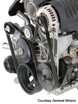 goes around a pulley connected to the front of the
engine's crankshaft and is usually responsible for driving a
number of other components including the water pump, power steering pump and air conditioning compressor. On some
engines, there is more than one belt and the task of driving
these components is divided between them. These belts
are usually referred to as: Fan Belt, Alternator Belt, Drive
Belt, Power Steering Belt, A/C Belt, etc. More common on
late model engines, one belt, called a Serpentine Belt will snake around the front of the engine and drive all the
components by itself.
goes around a pulley connected to the front of the
engine's crankshaft and is usually responsible for driving a
number of other components including the water pump, power steering pump and air conditioning compressor. On some
engines, there is more than one belt and the task of driving
these components is divided between them. These belts
are usually referred to as: Fan Belt, Alternator Belt, Drive
Belt, Power Steering Belt, A/C Belt, etc. More common on
late model engines, one belt, called a Serpentine Belt will snake around the front of the engine and drive all the
components by itself.
On engines with separate belts for each
component, the belts will require periodic adjustments to
maintain the proper belt tension. On engines that use a serpentine belt, there is usually a spring loaded belt
tensioner that maintains the tension of the belt, so no
periodic adjustments are required. A serpentine belt is
designed to last around 30,000 miles. Check your owner's
manual to see how often yours should be replaced.
Alternator output is measured in both voltage
and amperage. To understand voltage and amperage, you
must also know about resistance, which is measured in
ohms. An easy way to picture this is to compare the
movement of electricity to that of running water. Water
flows through a pipe with a certain amount of pressure.
The size (diameter) of the pipe dictates how much resistance
there will be to the flowing water. The smaller the
pipe, the more resistance. You can increase the pressure
to get more water to flow through, or you can increase the size of the pipe to allow more water to flow using less
pressure. Since too much pressure can burst the pipe, we should probably restrict the amount of pressure being
used. You get the idea, but how is this related to the
flow of electricity?
Well, voltage is the same as water
pressure. Amperage is like the amount or volume of water
flowing through, while resistance is the size of the wire
transmitting the current. Since too much voltage will
damage the electrical components such as light bulbs and
computer circuits, we must limit the amount of
voltage. This is the job of the voltage regulator.
Too much water pressure and things could start breaking.
Too much voltage and things could start burning out.
Let's
get technical
Now, let's go a little deeper and see how these
charging system components actually work to produce the
electrical power that a modern automobile requires.
 The alternator uses the
principle of electromagnetism to produce current. The
way this works is simple. If you take a strong magnet
and pass it across a wire, that wire will generate a small
voltage. Take that same wire and loop it many times,
than if you pass the same magnet across the bundle of loops,
you create a more sizable voltage in that wire.
The alternator uses the
principle of electromagnetism to produce current. The
way this works is simple. If you take a strong magnet
and pass it across a wire, that wire will generate a small
voltage. Take that same wire and loop it many times,
than if you pass the same magnet across the bundle of loops,
you create a more sizable voltage in that wire.
There are two main components that make up an
alternator. They are the rotor and the stator. The
rotor is connected directly to the alternator pulley.
The drive belt spins the pulley, which in turn spins the
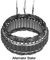
rotor. The stator is mounted to the body of the
alternator and remains stationary. There is just enough
room in the center of the stator for the rotor to fit and be
able to spin without making any contact.
The stator contains 3 sets of wires that have
many loops each and are evenly distributed to form a three
phase system. On some systems, the wires are connected
to each other at one end and are connected to a rectifier
assembly on the other end. On other systems, the wires
are connected to each other end to end, and at each of the
three connection points, there is also a connection to the
rectifier. More on what a rectifier is later.
The rotor contains the powerful
magnet that passes close to the many wire loops that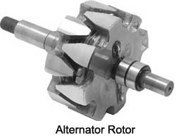 make up
the stator. The magnets in the rotor are actually
electro magnets, not a permanent magnets. This is done so that we can control how much voltage the alternator
produces by regulating the amount of current that creates the
magnetic field in the rotor. In this way, we can control
the output of the alternator to suit our needs, and protect
the circuits in the automobile from excessive voltage.
make up
the stator. The magnets in the rotor are actually
electro magnets, not a permanent magnets. This is done so that we can control how much voltage the alternator
produces by regulating the amount of current that creates the
magnetic field in the rotor. In this way, we can control
the output of the alternator to suit our needs, and protect
the circuits in the automobile from excessive voltage.
Now we know that every magnet has a north and a south pole and electro magnets are no exception. Our
rotor has two interlocking sections of electro magnets that
are arranged so that there are fingers of alternating north
and south poles. that are evenly distributed on the outside of
the rotor.
When we spin the rotor inside the stator and apply current
to the rotor through a pair of brushes that make constant
contact with two slip rings on the rotor shaft. This
causes the rotor to become magnetized. The alternating
north and south pole magnets spin past the three sets of wire
loops in the stator and produce a constantly reversing voltage
in the three wires. In other words, we are producing
alternating current in the stator.
Now, we have to convert this alternating current
to direct current. This is done by using a series of 6 diodes that are mounted in a rectifier
assembly. A diode allows current to flow only in
one direction. If voltage tries to flow in the
other direction, it is blocked. The six diodes are
arranged so that all the voltage coming from the alternator is
aligned in one direction thereby converting AC current into DC
current.
 There are 2 diodes for each of
the three sets of windings in the stator. The two diodes
are facing in opposite directions, one with its north pole
facing the windings and the other with its south pole facing
the windings. This arrangement causes the AC current
coming out of the windings to be converted to DC current before it leaves the alternator through the B terminal.
Connected to the B terminal of the alternator is a fairly
heavy wire that runs straight to the battery.
There are 2 diodes for each of
the three sets of windings in the stator. The two diodes
are facing in opposite directions, one with its north pole
facing the windings and the other with its south pole facing
the windings. This arrangement causes the AC current
coming out of the windings to be converted to DC current before it leaves the alternator through the B terminal.
Connected to the B terminal of the alternator is a fairly
heavy wire that runs straight to the battery.
Current to generate the magnetic field in the
rotor comes from the ignition switch and passes through the
voltage regulator. Since the rotor is spinning, we need
a way to connect this current from the regulator to the spinning rotor. This is accomplished by wires connected
to two spring loaded brushes that rub against two slip rings
on the rotor's shaft. The voltage regulator monitors the
voltage coming out of the alternator and, when it reaches a
threshold of about 14.5 volts, the regulator reduces the
current in the rotor to weaken the magnetic field. When
the voltage drops below this threshold, the current to the
rotor is increased.
There is another circuit in the
alternator to control the charging system warning lamp that
is on the dash. Part of that circuit is another set of
diodes mounted inside the alternator called the diode trio.
The diode trio takes current coming from the three stator
windings and passes a small amount through three diodes so
that only the positive voltage comes through. After
the diodes, the wires are joined into one wire and sent out
of the alternator at the L connection. It then goes to
one side of the dash warning lamp that is used to tell you
when there is a problem with the charging system. The
other side of the lamp is connected to the run side of the
ignition switch. If both sides of the warning lamp have equal
positive voltage, the lamp will not light. Remove
voltage from one side and the lamp comes on to let you know
there is a problem.
This system is not very efficient. There
are many types of malfunctions of the charging system that it
cannot detect, so just because the lamp is not lit does not
mean everything is ok. A volt meter is probably the best
method of determining whether the charging system is working
properly.
The voltage regulator can be mounted inside or
outside of the alternator housing. If the regulator is
mounted outside (common on some Ford products) there will be a
wiring harness connecting it to the alternator.
The voltage regulator controls the field current
applied to the spinning rotor inside the alternator. When
there is no current applied to the field, there is no voltage
produced from the alternator. When voltage drops below 13.5
volts, the regulator will apply current to the field and the
alternator will start charging. When the voltage exceeds 14.5
volts, the regulator will stop supplying voltage to the field
and the alternator will stop charging. This is how voltage
output from the alternator is regulated. Amperage or current
is regulated by the state of charge of the battery. When the battery is weak, the electromotive force (voltage) is not strong enough to hold back the current from the alternator
trying to recharge the battery. As the battery reaches a state
of full charge, the electromotive force becomes strong enough
to oppose the current flow from the alternator, the amperage
output from the alternator will drop to close to zero, while
the voltage will remain at 13.5 to 14.5. When more electrical
power is used, the electromotive force will reduce and
alternator amperage will increase. It is extremely important
that when alternator efficiency is checked, both voltage and
amperage outputs are checked. Each alternator has a rated
amperage output depending on the electrical requirements of
the vehicle.
Charging system gauge or warning
lamp
The charging system gauge or warning lamp monitors the
health of the charging system so that you have a warning of a
problem before you get stuck.
When a charging problem is indicated, you can still drive a short distance to find help unlike an oil pressure or coolant
temperature problem which can cause serious engine damage if
you continue to drive. The worst that can happen with a
charging system problem is that you get stuck in a bad
location.
A charging system warning lamp is a poor indicator of
problems in that there are many charging problems that it will
not recognize. If it does light while you are driving, it
usually means the charging system is not working at all. The
most common cause of this is a broken alternator belt.
There are two types of gauges used to monitor charging systems on some vehicles: a voltmeter which measures system
voltage and an ammeter which measures amperage. Most modern
cars that have gauges use a voltmeter because it is a much better indicator of charging system health. A mechanic's
voltmeter is usually the first tool a technician uses when
checking out a charging system.
A modern automobile has a 12
volt electrical system. A fully charged battery will read
about 12.5 volts when the engine is not running. When the
engine is running, the charging system takes over so that the
voltmeter will read 14 to 14.5 volts and should stay there
unless there is a heavy load on the electrical system such as
wipers, lights, heater and rear defogger all operating
together while the engine is idling at which time the voltage
may drop. If the voltage drops below 12.5, it means that the battery is providing some of the current. You may notice that
your dash lights dim at this point. If this happens for an
extended period, the battery will run down and may not have
enough of a charge to start the car after shutting it
off. This should never happen with a healthy charging system because as soon as you step on the gas, the charging system will recharge the battery. If the voltage is
constantly below 14 volts, you should have the system checked.
If the voltage ever goes above 15 volts, there is a problem
with the voltage regulator. Have the system checked as soon as
possible as this "overcharging" condition can cause damage to
your electrical system.
stay there
unless there is a heavy load on the electrical system such as
wipers, lights, heater and rear defogger all operating
together while the engine is idling at which time the voltage
may drop. If the voltage drops below 12.5, it means that the battery is providing some of the current. You may notice that
your dash lights dim at this point. If this happens for an
extended period, the battery will run down and may not have
enough of a charge to start the car after shutting it
off. This should never happen with a healthy charging system because as soon as you step on the gas, the charging system will recharge the battery. If the voltage is
constantly below 14 volts, you should have the system checked.
If the voltage ever goes above 15 volts, there is a problem
with the voltage regulator. Have the system checked as soon as
possible as this "overcharging" condition can cause damage to
your electrical system.
 If you think of electricity as
water, voltage is like water pressure, whereas amperage is
like the volume of water. If you increase pressure, then
more water will flow through a given size pipe, but if you
increase the size of the pipe, more water will flow at a lower
pressure. An ammeter will read from a negative amperage
when the battery is providing most of the current thereby
depleting itself, to a positive amperage if most of the
current is coming from the charging system. If the battery is fully charged and there is minimal electrical
demand, then the ammeter should read close to zero, but should
always be on the positive side of zero. It is normal for the
ammeter to read a high positive amperage in order to recharge
the battery after starting, but it should taper off in a few
minutes. If it continues to read more than 10 or 20 amps
even though the lights, wipers and other electrical devices
are turned off, you may have a weak battery and should have it
checked.
If you think of electricity as
water, voltage is like water pressure, whereas amperage is
like the volume of water. If you increase pressure, then
more water will flow through a given size pipe, but if you
increase the size of the pipe, more water will flow at a lower
pressure. An ammeter will read from a negative amperage
when the battery is providing most of the current thereby
depleting itself, to a positive amperage if most of the
current is coming from the charging system. If the battery is fully charged and there is minimal electrical
demand, then the ammeter should read close to zero, but should
always be on the positive side of zero. It is normal for the
ammeter to read a high positive amperage in order to recharge
the battery after starting, but it should taper off in a few
minutes. If it continues to read more than 10 or 20 amps
even though the lights, wipers and other electrical devices
are turned off, you may have a weak battery and should have it
checked.
What can go wrong?
There are a number of things that can go wrong
with a charging system:
Insufficient Charging
Output
If one of the three stator windings
failed, the alternator would still charge, but only at two
thirds of its normal output. Since an alternator is
designed to handle all the power that is needed under heavy
load conditions, you may never know that there is a problem
with the unit. It might only become apparent on a
dark, cold rainy night when the lights, heater, windshield
wipers and possible the seat heaters and rear defroster are
all on at once that you may notice the lights start to dim
as you slow down. If two sets of windings failed, you
will probably notice it a lot sooner.
It is more
common for one or more of the six diodes in the rectifier to
fail. If a diode burns out and opens one of the
circuits, you would see the same problem as if one of the
windings had failed. The alternator will run at a
reduced output. However, if one of the diodes were to short out and allow current to pass in either direction,
other problems will occur. A shorted diode will allow
AC current to pass through to the automobile's electrical system which can cause problems with the computerized sensors and processors. This condition can cause the
car to act unpredictably and cause all kinds of
problems.
Too much
voltage
A voltage regulator is designed to
limit the voltage output of an alternator to 14.5 volts or
less to protect the vehicle's electrical system. If
the regulator malfunctions and allows uncontrolled voltage
to be released, you will see bulbs and other electrical
components begin to fail. This is a dangerous and
potentially costly problem. Fortunately, this type of
failure is very rare. Most failures cause a reduction
of voltage or amperage.
Noise
Since
the rotor is always spinning while the engine is running,
there needs to be bearings to support the shaft and allow it
to spin freely. If one of those bearings were to fail,
you will hear a grinding noise coming from the
alternator. A mechanic's stethoscope can be used to
confirm which of the spinning components driven by the serpentine belt is making the noise.
Repairing Charging
System Problems
The most common repair is the replacement of the
alternator with a new or rebuilt one. A properly rebuilt
alternator is as good as a new alternator and can cost
hundreds less than purchasing a brand new one.
Labor time to replace an alternator is typically
under an hour unless your alternator is in a hard to access
location. Most alternators are easily accessible and
visible on the top of the engine.
Replacing an alternator is usually an easy task
for a backyard mechanic and rebuilt alternators are readily
available for most vehicles at the local auto parts store. The most important task for the do-it-yourselfer
is to be careful not to short anything out.
ALWAYS
DISCOnnECT THE BATTERY BEFORE REPLACING AN ALTERNATOR.
Alternators can be repaired by a knowledgeable
technician, but in most cases, it is not economical to do
this. Also, since the rest of the alternator is not
touched, a repair job is usually not guaranteed.
In some cases, if the problem is diagnosed as a bad voltage regulator, the regulator can be replaced without springing for a complete rebuild. The problem with this
is that there will be an extra labor charge for disassembling
the alternator in order to get to the internal
regulator. That extra cost, along with the cost of the
replacement regulator, will bring the total cost close to the
cost of a complete (and guaranteed) rebuilt.
This is not the case when the regulator is not
inside the alternator. In those cases, the usual
practice is to just replace the part that is bad.